
|
Starter Solenoid R/R - 22 Oct 2005.
- Detach wire strand from solenoid.
- Remove retaining bolts of solenoid from the drive housing.
- Pull Starter pinion out somewhat and withdraw solenoid switch. Defective
solenoids should be replaced with new ...
|
|
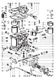
Description of the Solex 40 P II - 4 Carburetor - 12 Aug 2005.
This diagram is for the early cars.
Later cars.
The Type 912 Porsche is equipped with two SOLEX 40 P II - 4
double-throat downdraft carburetors. The induction throats are 40 mm
(1.575in) in diameter. Since the ...
|

|
Adjusting Gearshift Linkage - 24 Jan 2005.
- 1. Remove retaining screws from cover in rear of center tunnel and
withdraw cover.
- 2. Loosen hex bolt in shift rod clamp.
- 3. Move selector shaft of internal shift lever in transmission all
the way left ...
|

|
Heat Exchanger with Exhaust Pipe R/R - 19 Jan 2005.
Engine removed, applicable to 356B/T6 Heaters.
Remove engine rear shield.
Detach clamps from holders.
Remove exhaust muffler (12 En)
Remove nuts from front and rear flanges
Remove securing claws from ...
|
|
Flywheel R/R - 17 Jan 2005.
P 44 Hex socket (36 mm)
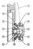
The flywheel is attached to the crankshaft by way of a gland nut;
eight dowel pins transmit the torque forces. A soft iron gasket is
installed between the flywheel and the crankshaft. Oil ...
|

|
Removing and Installing Exhaust Muffler - 17 Jan 2005.
This procedure refers specifically to the German/Swedish version of the
heating system.
1. Remove both supports for engine rear shield.
2. Loosen the four exhaust pipe clamps behind the heat exchangers.
3. ...
|

|
912 Manual Replace Cooling Blower - 17 Jan 2005.
Parts diagram of the fan and associated plates.
The detachable generator carrier permits withdrawal of the generator
and blower impeller assembly without removal of the entire air blower
housing. The work procedure ...
|

|
Adjusting Clutch Travel Limits - 17 Jan 2005.
The diaphragm spring clutch requires an exactly limited clutch pedal
travel. Whenever work has been performed on the clutch, check and
correctly adjust the clutch pedal travel.
Bring transmission to operating ...
|

|
Adjusting Clutch - 17 Jan 2005.
Both ends of the clutch cable have threads and may be adjusted at
either the clutch control lever in transmission housing or at the
clutch pedal. The clutch is correctly adjusted when clutch pedal free
travel is 20 - ...
|

|
Inspecting Clutch Assembly - 17 Jan 2005.
The Fichtel-Sachs MX 200 K clutch has been designed without provision
for repair or overhaul. The clutch inspection is, therefore, limited
to a thorough visual examination of the component parts.
1. Clean the ...
|

|
Inspecting Clutch Disk - 17 Jan 2005.
1. The clutch linings are riveted to undulated spring segments which
curve from side to side and provide a cushioning effect in the clutch
disc. It is essential for proper functioning of the clutch that ...
|

|
Clutch R/R - 17 Jan 2005.
Remove engine and detach from transmission.
Evenly loosen clutch retaining bolts, slackening each by one or two
turns at a time and switching in a cross sequence until the spring
pressure is relieved, to a void ...
|

|
912 Manual Cooling System Replace - 17 Jan 2005.
Detatch the throttle linkage.
Remove carburetors, throttle linkage and generator retaining strap.
Detach oil filter.
Disconnect distributor and retaining screws from the side shrouds.
Lift the blowing howing ...
|

|
Description of the Clutch - 17 Jan 2005.
A dry single plate clutch is incorporated in the flywheel between
engine and transmission. The spring cushioned clutch disc has friction
linings on both sides. It rides in the splined input shaft and has
axial freedom ...
|
|
Reconditioning Crankshaft - 17 Jan 2005.
Crankshafts can only be reground at the factory and/or obtained
through the exchange service, as these crankshafts demand a special
treatment of material. Appropriate undersize bearings are available
within the spare ...
|

|
Checking and Adjusting Crankshaft End Play - 17 Jan 2005.
P 17 Dial gauge holder, for mea suring end play in assembled engine.
End play should be 0,14 - 0,17 mm ( 0.0055 to 0.0067 in), wear limit 0,22
mm ( 0.0087 in). End play should be adjusted before installing ...
|
|
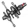
Disassembling and Reassembling Crankshaft - 17 Jan 2005.
VW 161a Lock ring pliers, for removing and installing gear lock ring
on crankshaft.
VW 202 Puller with
- VW 202a Puller jaws
- VW 202f Block -- for removing gears from crankshaft
VW 310a Crankshaft bench ...
|
|
Measuring and Realigning Connecting Rods - 17 Jan 2005.
P 14b Connecting rod measuring fixture
- Remove crankshaft and take off connecting rods, Mark connecting
rods and caps to ensure reassembly in original locations and posi
tions.
- Remove bearing inserts.
- ...
|

|
Installing Connecting Rod Bushings - 17 Jan 2005.
(Connecting rods removed from engine)
If clearance between piston pin and bushing is excessive, install new
bushings in the connecting rods by noting the following points:
Install new bushings on a press using a ...
|

|
Connecting Rods R/R - 17 Jan 2005.
VW 310a Crankshaft bench mount
Remove crankshaft and place into VW 310a bench mount (50 En).
Remove connecting rod retaining nuts, remove connecting rods and caps.
Installation is accomplished in reversed ...
|

|
Crankshaft with Connecting Rods R/R - 17 Jan 2005.
Disassemble crankcase (41 En).
Withdraw camshaft.
Remove crankshaft with connecting rods.
Mark insert of Bearing 2 and 3.
Installation is accomplished by noting the following points:
Lightly bevel ...
|

|
912 Manual Replace Hoses, Ducts and Gates - 17 Jan 2005.
Detach heating hose.
Show how to disconnect the Euro hoses.
How to adjust the Euro Hose Installation
This is for the export heater. The following points should be
observed when installing the lower air ...
|

|
Flywheel Oil Seal R/R - 17 Jan 2005.
VW 204b Crankshaft oil seal installer
Remove flywheel. Inspect oil sealing surface on flywheel hub.
Remove old oil seal.
Clean the oil seal seat and apply a thin coat of gasket compound, If
necessary, ...
|

|
912 Manual Cooling System Removal - 17 Jan 2005.
The cooling air shroud guides the cooling air to the cooling points. It
is important to accomplish the assembly with care. The shrouds have to
be installed in such way that no open areas or slits are created ...
|
|
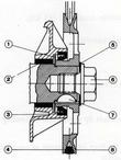
Crankshaft Pulley R/R - 17 Jan 2005.
Oil deflector
Bearing 4
Oil seal
V-belt
Spring washer
Retaining bolt
Woodruff key
Crankshaft pulley
Remove V-belt.
Remove engine rear shield.
Remove crankshaft pulley retaining bolt. ...
|

|
Engine Lubrication System - 17 Jan 2005.
Oil Circuit in a Cold Engine
Oil Circuit at Operating Temperature
Remove and replace the Oil Strainer
1. Remove hex nuts from oil strainer cover.
2. Remove oil strainer cover.
3. Remove oil strainer ...
|

|
Electrical System Description - 17 Jan 2005.
A 12 volt, 300 watt generator is utilized, The alternator charges the
battery and supplies current to the electrical units of the car.
An 8/10 HP - solenoid-operated starter is utilized. The starter is
controlled ...
|

|
Generator Faults and their Elimination - 17 Jan 2005.
The red ignition warning light on the combination instrument should
light up when the ignition is switched on and should go out after the
engine has started and the engine speed has begun to rise.
The possible causes ...
|

|
Generator Description - 17 Jan 2005.
The generator has the function of supplying all the current consuming
units in the vehicle and to charge the battery satisfactorily. It is
driven by the engine by means of a V-belt. To regulate the voltage
which ...
|

|
Camshaft R/R - 17 Jan 2005.
Disassemble crankcase (41 En).
Withdraw camshaft.
Install camshaft by noting the following points:
1, Check for firm attachment of camshaft gear to camshaft.
2. Check camshaft for wear at bearing ...
|

|
Inspecting Pistons - 17 Jan 2005.
Piston diameter is indicated by size group stamped into the piston
top. The individual size groups are shown in the
[html:/912/manual22.html piston size table]. Piston measuring point is
shown in Fig. 137.
In order ...
|

|
Timing Gear Cover R/R - 17 Jan 2005.
1. Remove generator (5 En).
2. Remove generator carrier.
3. Remove distributor and distributor pinion shaft.
4. Remove fuel pump (13 Fu).
5. Remove crankshaft pulley (47 En). (See Note, below).
6. ...
|

|
Bearing 4 R/R - 17 Jan 2005.
P 27 a Assembly plate for removing and installing Bearing 4
P 73 Installer for oil seal at Bearing 4
1. Remove timing gear cover (45 En).
2. Deform old oil seal by striking it with hammer and punch ...
|

|
Removing and Installing Oll Seal at Bearing 4 - 17 Jan 2005.
P 73 Installer for oil seal at Bearing 4
1. Remove crankshaft pulley (47 En).
2. Withdraw Woodruff key.
3. Deform old oil seal by striking it with hammer and punch through
the recess slot in the seal sea t, ...
|

|
Distributor Pinion Shaft R/R - 17 Jan 2005.
1. Remove distributor cap.
2. Detach connecting wire from distributor.
3. Remove hex nut which holds distributor base plate.
4. Withdraw distributor.
5. Remove fuel pump, insulating flange, gaskets, and ...
|

|
Crankcase Disassembling and Reassembling - 17 Jan 2005.
P 44 Hex socket (36 mm)
P 49 Retaining Springs
1. Remove oil drain plug.
2. Remove oil cooler.
3. Remove flywheel (46 En).
4. Remove oil pressure switch.
5. Remove oil pressure relief valve. ...
|

|
Piston Size Table - 17 Jan 2005.
| Piston Dia. +/- 0.005 mm | Stamped Marking | Size Group |
| 82,49 | + 1 | |
| 82,48 | 0 | Standard size |
| 82.47 | - 1 | |
| 82,99 | + 1 KD 1 | |
| 82,98 | 0 KD 1 | 1st oversize |
|| 82,97|| - 1 KD 1|| ...
|

|
Lamps and Fuses - 17 Jan 2005.
High beam, left
High beam, right High beam indicator
Low beam, left
Low beam, right
Parking lamp, left
Parking lamp, right
License plate lamp and luggage compartment lamp
Fog lamps
Windshield ...
|

|
Checking Field Coils - 17 Jan 2005.
Both field coils should be checked for open circuit, winding and earth shorts.
Check each field coil separately for open circuit connecting its
ends with a 12 V test lamp in series with the battery. In the case ...
|

|
Changing Ignition Warning Light - 17 Jan 2005.
The ignition warning light (red) is connected between the B+ terminal
and 61 of the regulator switch of the generator and lights up in the
combination instrument on the instrument panel when the ignition is
switched ...
|

|
912 Manual - 17 Jan 2005.
The 912 manual is a slim edition that supplements the 911 manual for
the same period. It covers the major differences between the two
models.
The engine shown is for a 1965-1966 SWB car and has the German ...
|

|
912 Manual Engine Disassembly - 17 Jan 2005.
The description leaves out a significant amount of information. A much
better description is found in Harry Pellow's Secrets of the Inner
Circle
The maunal calls out some special tools that are used for ...
|

|
Remove and Install Rocker Arm Carrier - 17 Jan 2005.
1. Remove rocker box cover.
2. Remove the 7 hex nuts (SW 13) from the . rocker arm shafts.
- 3. Withdraw rocker arm shafts with rocker arms, springs, washers and
spacers.
- 4. Remove the three rocker arm ...
|

|
R/R Cylinder Head - 17 Jan 2005.
VW 157 Allen wrench adapter
VW 118 Torque wrench
This section assumes the engine is removed.
1. Remove lower air duct, side shield, cylinder shrouds, intake duct
and carburetor.
2. Remove rocker box ...
|
|
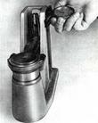
Removing and Installing Valve Springs - 17 Jan 2005.
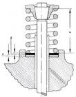
Use special tool P7 for removing and installing valve springs.
| Free length | 47 mm (1,85in) |
| Wire diameter | 4.5 mm (. 177in) |
||Spring tension with spring compressed to 41 mm (1. 61in)||36kp(79, 3lbs) +/- ...
|
|
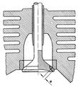
Checking and Reconditioning Valve Seats - 17 Jan 2005.
P 11 Valve seat cutter handle with 10 mm dia. cutter guide
P 12 Eight-piece valve seat cutter set.
- Check valve guides for firm seating in the cylinder head.
- Check valve seating using machinists blue.
- ...
|

|
Seating, Inspecting and Testing Valves - 17 Jan 2005.
P 9 Suction cup, for turning valve The following points should be
observed when seating (lapping) valves:
The following points should be observed when seating (lapping) valves:
Seat valve with the P 9 suction ...
|

|
Adjusting Valve Clearance - 17 Jan 2005.
Intake   0.10 mm (0.004 in)
Exhaust  0.15 mm (0.006 in)
Excessive clearance causes valve noise and decreased power.
Insufficient clearance results in decreased power, valve overheating
or burning, and ...
|

|
Reconditioning and Exchange of Cylinder Heads - 17 Jan 2005.
Cylinder heads with worn valve guides, valve seats. or spark plug
inserts may be sent to the factory for reconditioning.
When the cylinder heads are being reconditioned, the combustion
chamber displacement is measured ...
|

|
Removing and Installing Cylinders - 17 Jan 2005.
P 8a Piston ring compressor, 82.5 mm diameter.
1. Remove rocker arms and rocker arm carrier, Remove valve pushrods
and mark for reassembly.
2. Remove cylinder head and push rod cover tubes (25 En).
3. Withdraw ...
|

|
Inspecting Cylinders - 17 Jan 2005.
P 13c Cylinder gauge setting ring
(Note: 1 mm = 0,03937 in)
| Group | Cylinder Diameter | Piston Diameter |
| -1 | 82,485 - 82,494 | 82,47 |
| 0 | 82,495 - 82,504 | 82,48 |
|| +1|| 82,505 - 82,514|| 82,49 ...
|

|
912 Manual - Engine Assembly - 17 Jan 2005.
Again, the description leaves out a significant amount of
information. A much better description is found in Harry
Pellow's Secrets of the Inner Circle
Now we can start putting the engine back ...
|

|
Removing and Installing Pistons - 17 Jan 2005.
P 1a Electric piston heater P 2 Piston pin mandrel
The piston pins are arranged in the pistons off the center and it is,
therefore, important to correctly install the pistons in the
engine. The piston top bears ...
|
|
912 Manual Checking and Adjusting V-Belt Tension - 17 Jan 2005.
The generator and air blower are driven by a V-belt. The loads created
by these two accessory units impose considerable stresses upon the
belt at high engine speeds and, especially, during downshifts. For
this ...
|
|
Checking Armature - 15 Jan 2005.
Armature faults are in many cases not externally visible. Checking
should include tracing of open circuits as well as winding and earth
shorts.
1. Open circuits are generally recognizable on the commutator by ...
|

|
Dismantling and Reassembling Generator - 15 Jan 2005.
Detach V-belt pulley and cooling fan.
Undo field coil connection from brush holder of positive brush.
Undo both generator housing bolts.
Take generator housing apart and extract armature.
Pull out ball ...
|

|
Removing and Refitting Generator - 15 Jan 2005.
Disconnect cable at generator.
Detach V -belt.
Remove clamp strip of generator.
Undo fixing bolts on generator bracket.
Undo four bolts on fan cover and extract generator.
When refitting the following ...
|

|
Checking Carbon Brushes and Commutator - 15 Jan 2005.
Undo cover strap of generator.
Check carbon brushes for wear and free travel in the brush holder
guides. Brushes which completely disappear into the brush holder are
worn and must be replaced; the same applied to ...
|

|
Removing and Refitting Regulator Switch - 15 Jan 2005.
Disconnect battery.
Remove leads from regulator.
Undo fixing bolts and detach regula tor.
The following should be noted:
When exchanging the regulator first check that there is no short
to earth in the ...
|

|
Checking the Generator - 15 Jan 2005.
For checking the electrical system the following test instruments are
required: One Voltmeter range 0 - 20 Volts
One voltmeter range 0 - 20 Volts.
One ammeter range 10 - 0 - 60 Amps.
Load resistance ...
|

|
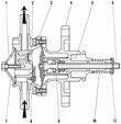
Disassembling and Reassembling Starter - 15 Jan 2005.
...
|
|
Fuel Pump Description - 12 Jan 2005.
Cross sectional view of the the fuel pump with major pieces named.
The fuel is pumped to the carburetors by a mechanical diaphragm pump
which is mounted on the engine crankcase. The fuel pump is actuated by
an ...
|

|
Carburetor Service Diagnosis - 12 Jan 2005.
The chart applies only to carburetors which meet specifications shown
on page F 11.
| Malfunction | Possible Cause | Remedy |
|---|
|
1. Engine ...
|

|
Fuel System Description - 12 Jan 2005.
Fuel tank
Fuel lines
Mechanical fuel pump
Two double - throat downdraft carburetors with air cleaner
The fuel tank is located under the front lid beneath the luggage
compartment. It has a capacity of ...
|

|
Carburetor Specifications - 12 Jan 2005.
| Carburetor type | Solex 40 P II-4 | 2 per engine |
| Venturi (K) | 32 | 2 per carburetor |
| Main jet (Gg) | 0120 | 2 per carburetor |
| Air correction jet (a) | 180 | 2 per carburetor |
||Idle metering jet (g)|| ...
|

|
Removing and Installing Carburetor - 10 Jan 2005.
- Unsnap air cleaner fasteners.
- Remove air cleaner.
- Remove air cleaner base plate.
- Detach carburetor linkage from throttle arm.
- Detach fuel line.
- Remove four carburetor retaining nuts from carburetor ...
|

|
Tolerances and wear Limits - 08 Jan 2005.
| Measuring point | Tolerance (new) | Wear Limit | |
| 1. Cylinder seat depth in cylinder head | 9.500-9.600 mm (0.374-0.378 in) | 10.000 mmm (0.3937 in) |  |
||2. Cylinder bore ovality, B minus ...
|

|
Removing and Installing Air Cleaners - 21 Dec 2004.
Detach carburetor heating hose,
Unsnap all four fasteners at the lower part of the air cleaner
housing (KNECHT-Filter),
Detach crankcase breather hose from the air cleaner housing.
Withdraw the air ...
|

|
Adjusting Idle Speed - 21 Dec 2004.
P 227 Carburetor Synchronizer
Remove idle mixture adjusting screws and inspect needle tips for
burrs, grooves, and bends. Install new screws if in doubt,
Bring engine to normal operating temperature and ...
|

|
Adjusting Injection Quantity - 21 Dec 2004.
P 25a Calibrated Vial
Adjusting idle speed.
Run engine to fill float chamber with fuel.
Stop engine, remove both air cleaners.
Work throttle arm until air bubbles cease to show at the pump
injection ...
|

|
Disassembling and Reassembling Carburetor - 21 Dec 2004.
Remove carburetor
Remove retaining screws from carburetor cover, withdraw cover with gasket.
Remove float with pin and intermediate swivel joint.
Remove four accelerating pump retaining ...
|

|
Cleaning Carburetor - 21 Dec 2004.
Remove carburetor.
Wash carburetor with clean solvent.
Remove retaining screws from carburetor cover.
Withdraw carburetor cover, watch float pin retainers.
Remove float pin and float. ...
|

|
Removing and Installing Intake Duct - 21 Dec 2004.
Remove carburetor.
Remove spark plug connectors from spark plugs.
Remove side cover plate.
Remove retaining nuts and bolt from intake duct and withdraw duct.
Cover intake port ...
|

|
Reconditioning Fuel Pump - 21 Dec 2004.
Remove cover retaining hex bolt.
Remove cover and fuel screen.
Remove six fillister screws which secure the upper assembly, withdraw assembly.
Rest the lower assembly of pump on the diaphragm ...
|

|
Removing and Installing Fuel Pump - 21 Dec 2004.
Remove fuel hoses from pump.
Remove pump shield.
Remove pump attaching nuts from flange.
Remove pump and insulating spacer.
Installation is accomplished in reversed order of the above. ...
|

|
Testing Pump Pressure - 21 Dec 2004.
The pump pressure is determined by the degree of spring compression
during the intake stroke of the pump. The spring tension is so
calibrated that it allows,the fuel to enter the carburetor only as
long as the float ...
|

|
Adjusting Throttle Linkage - 21 Dec 2004.
The throttle linkage must be so adjusted that all throttle valves work
in unison. In addition it should be noted that the throttles do not
bind throughout the entire extent of travel from idle to full ...
|

|
Removing and Installing Throttle Linkage - 21 Dec 2004.
Remove floor mat to gain access to opening in floorboard.
Detach throttle rod at ball joint of cross-shaft at air blower housing.
Remove gearshift lever base retaining screw (hex head).
Withdraw ...
|

|
Removing and Installing Fuel Line - 21 Dec 2004.
Remove both air cleaners.
Detach fuel line from both carburetors by removing connectors.
Remove attaching clip from air blower housing.
Withdraw fuel hose from fuel pump.
Reassemble in reversed order of ...
|

|
Checking Carburetor Float Level - 21 Dec 2004.
Special Tools: P 78 Float Level Gauge
1. Place car on level base.
2. Remove main jet carrier from one carburetor.
3. Install float level gauge (P 78) in place of main jet carrier.
4. Start engine and allow ...
|

|
Torque Values for Bolts and Nuts - 15 Dec 2004.
(1 mkp = 7.233 lbs/ft)
| Fastener | mkp | lbs/ft |
| Crankcase bolts | 2.5 | 18 |
| Timing gear cover nuts | 2.0 | 14.5 |
| Connecting rod nuts (without safety plates) | 4.5 | 32.5 |
||Cap nuts for through - ...
|

|
Description of the Export - Type Heating System - 14 Dec 2004.
The entire fresh air mass enters through slots in the engine
compartment lid (1). being drawn in by the cooling air blower (2). The
air blower forces the air over the cylinders (3) where it is
preheated, and on to ...
|

|
Description of the 356B/T6 Heating System - 14 Dec 2004.
Due to varying laws in force, it is necessary to equip The Type 912
cars with two different heating systems. Cars manufactured for sale in
Germany and Sweden are equipped with a modified heating system known
as 356 ...
|

|
Refacing Valves - 09 Dec 2004.
Valves showing face wear of a degree that cannot be corrected through
lapping, may be dressed on a valve refacing machine. Refacing of the
valves must be accomplished with appropriate care. Particular
attention ...
|

|
Checking Valve Guides for Wear - 09 Dec 2004.
Special Tools: P 21b Valve guide plug gauge
See:
Replacing of valve guides see 35 EN.
Clearance between valve guide bore and valve stem is:

Intake = 0.035 - 0.060 mm ( 0.0014in to 0.0024in)
Exhaust = 0.055 ...
|

|
Disassembling and Reassembling Rocker Arm Carrier - 09 Dec 2004.
- 1. Remove the 7 hex nuts (SW 13) from the rocker arm shafts.
- 2. Withdraw rocker arm shafts with rocker arms, springs, washers,
and spacers.
- 3. Remove valve adjusting screws.
Reassemble the rocker arm ...
|
|


