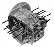
Crankcase Disassembling and Reassembling
Special Tools:
- P 44 Hex socket (36 mm)
- P 49 Retaining Springs
Disassembly
| - 1. Remove oil drain plug.
- 2. Remove oil cooler.
- 3. Remove flywheel (46 En).
- 4. Remove oil pressure switch.
- 5. Remove oil pressure relief valve.
|
| - 6. Remove oil strainer and magnetic filtering element.
- 7. Remove fuel pump insulating flange.
- 8. Remove distributor and distributor pinion shaft.
- 9. Remove crankshaft pulley and Woodruff key.
- 10. Remove pulley shield.
- 11. Remove oil pump
|
| - 12. Remove generator carrier.
- 13. Remove timing gear cover.
|
| - 14. Remove crankcase retaining nuts.
- 15. Remove crankcase retaining nuts at camshaft end (flywheel side).
- 16. Withdraw right crankcase half using a rubber mallet if
necessary. Do not pry with sharp tools, such as a screw driver, as
this could damage the mating surfaces.
- 17. Remove valve lifters.
- 18. Withdraw camshaft and crankshaft.
- 19. Remove camshaft end cap.
- 20. Remove crankshaft oil seal at Bearing 1.
- 21. Withdraw Bearing 2 and 3.
|
Reassembly
Reassembly is accomplished in reversed order of the above by noting
the following points:
| - 1. Inspect crankcase and timing gear cover for cracks or damage.
- 2. Using an appropriate solvent, remove sealing compound remnants
from crankcase mating surfaces.
- 3. Check mating surfaces for linear alignment and cleanliness.
- 4. Assemble empty crankcase and tighten retaining nuts. Using an
inside micrometer, measure main bearing bores.
- 5. If necessary, lightly break the sharp edges from main bearings
bores.
- 6. Flush oil passages with solvent and blow trough with compressed
air.
- 7. Check oil suction tube for firm seating and tightness; if
necessary, re-fasten with P 50a ball end punch.
- 8. Check valve lifters and lifter guide bores.
- 9. Check firm seating of dowel pins aligning timing gear cover.
- 10. Insert main bearing dowel pins. Install main bearing inserts for
Bearing 2 and 3- place the insert half which has the oil passage into
the left crankcase half making sure that the passage in the insert
lines up with the passage in the crankcase bearing seat; install the
other insert halves in the right crankcase half.
- 11. Install crankshaft and camshaft, check for free rotation.
- 12. Install thrust washer, crankshaft oil seal and Bearing 1.
- 13. Note correct positioning of timing gears. (See Fig. 142).
|
| - 14. Install camshaft end plug, seal with gasket compound.
- 15. Secure valve lifters with P 49 retaining springs.
- 16. Apply a thin, uniform coat of gasket compound to crankcase mating
surfaces, Make absolutely certain that no gasket compound enters oil
galleries of crankshaft and camshaft bearings.
- 17. Join crankcase halves.
- 18. Install a-rings and beveled washers fitted under cap nuts;
position the washers so that the inside bevel faces the crankcase to
accommodate the a,..rings, Tighten cap nuts to 4 mkp (29 lbs/ ft),
- 19. Tighten crankcase retaining nuts at camshaft end (flywheel side).
- 20. Install timing gear cover.
- 21. Tighten remaining crankcase retaining bolts to 3 mkp (21. 7 lbs/ft).
- 22. Tighten timing gear cover retaining nuts to 2 mkp (14. 5 lbs/ft).
- 23. Install new oil seal at Bearing 4 in timing gear cover,
- 24. Turn crankshaft to check for free rotation.
- 25. Install fuel pump insulating flange and fuel pump.
|
Last modified: Mon, 17 Jan 2005
Links
|