Engine Lubrication System
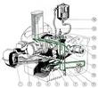
Oil Circuit Diagrams
|
Oil Circuit in a Cold Engine
|
|
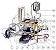
Oil Circuit at Operating Temperature
|
Oil Strainer
Removal
| Remove and replace the Oil Strainer
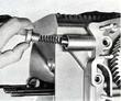
- 1. Remove hex nuts from oil strainer cover.
- 2. Remove oil strainer cover.
- 3. Remove oil strainer and gaskets.
|
Install
Installation is accomplished in reversed order of the above by noting
the following points:
- Check oil suction tube for proper positioning.
- Clean oil strainer and remove gasket remnants.
- Use new gaskets on both sides of the oil strainer.
- Insert oil strainer making sure that the orifice in the strainer has a close fit around the oil suction tube.
- Remove gasket remnants from the oil strainer cover. Straighten the cover if it is warped or bent, otherwise a good oil seal cannot be expected.
- Clean magnetic filtering element.
- Do not over tighten the hex retaining nuts, especially when using thicker gaskets, since this may warp the cover.
Note:
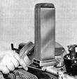
A magnetic oil filtering element has been included in the oil strainer
cover to provide for a better filtering of the oil. The element is
situated in the center of the oil strainer cover with the oil suction
tube located within it. The oil first passes through the oil screen
and then flows through the magnetic filtering element.
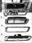
| Magnetic Oil Filter
- Crankcase
- Oil strainer
- Magnetic filter
- Oil suction tube
- Stud
- Oil strainer cover
- Disc
- Rivet
- Gasket
|
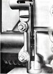
Pressure Relief Valve
Special Tools: P 74 Socket attachment
General
The pressure relief valve is located in the crankcase and governs
engine oil pressure.
When encountering malfunctions in the engine lubrication system, and
always in cases of leaks in the oil cooler, check the pressure relief
valve for proper functioning.
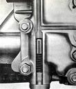
The bypass circuit valve is located in the timing gear cover and
ensures immediate lubrication of engine bearings and other points when
the engine is started.
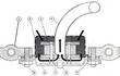
Functional Description of the Bypass Valve:
The purpose of the bypass valve in the timing gear cover is to provide
instant lubrication for points in the engine, by bypassing the oil
cooler, when the engine is started.
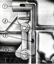
| - 1 Oil gallery to oil cooler
- 2 Oil gallery from oil pump
- 3 Oil gallery to lubricating points by bypassing the oil cooler
- 4 Opening for counter-pressure oil line.
|
| When the engine is not running, the valve (plunger) closes the passage
to the lubricating points. As soon as the engine begins to run, the
oil pump sucks oil from the oil sump in the crankcase and forces it to
the bypass valve. The bypass valve is then forced down, under the
pressure of the oil, and opens the oil gallery to the lubricating
points by bypassing the oil cooler.
|
| As soon as the oil pressure has built up, some of the oil flows
through the counter-pressure line to the cavity under the valve
plunger equally counteracting the pressure exerted by the oil from
above, permitting the mechanical spring to expand and, thus, push the
valve plunger up and close the oil gallery of the direct lubricating
circuit. This forces the oil to flow through the oil cooler before it
can reach the lubrication points within the engine.
|
Removal
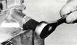
| 1. Remove cap screw with tool P 74.
|
| 2. Withdraw spring and valve plunger; if plunger is stuck, it can be
removed with an M 10 thread tap.
|
Installation
Installation is accomplished in reversed order of the above by noting
the following points:
- Inspect valve plunger and plunger bore in housing for traces of
seizure (scratches, etc.). Carefully smoothen the surfaces, replace if
necessary.
- Check mechanical spring
Pressure Relief Valve and Bypass Valve Spring
Free length............  66 mm (2.6in)
Wire diameter.........  1.4 mm (.055in)
Tension at 49 mm(1.93in).....4.7 kp (10.3 lbs) +/- 7%
- Install new gasket washer.
- Insert the piston so that its hollow end faces towards the cap screw.
- To prevent scratching the bore in the housing, make sure that the
spring end does not ride in the plunger bore in housing.
Oil Cooler
Removal
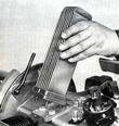
| - 1. Remove air blower housing (4 En).
- 2. Unscrew oil cooler retaining nuts with a box wrench. ..
|
| - 3. Remove oil cooler and gaskets.
|
Installation
Installation is accomplished in reversed order of the above by noting
the following points:
- Check oil cooler for leaks and proper tightness of retaining nuts
(test pressure is 10 atm-147 psi).
- If oil cooler is leaking, check pressure relief valve.
- Use new gaskets.
Oil Pump
Remove
| - Remove engine rear shield and intermediate shield between the air ducts.
- Remove crankshaft pulley.
- Remove crankshaft pulleys shield,
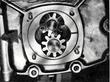
- Remove oil pump cover.
- Remove oil pump gears.
|
Installation
Follow reversed order
- Inspect oil pump housing, especially gear seating areas, for
wear. Wear within the housing will result in decreased oil pressure.
- Inspect pump gears for wear. Gear flank clearance should be O.03 -
O.O5 mm (.001 - .003in.). Axial play of gears in the housing, with
gasket but without preload, is 0.035 - O.10 mm (.0014 - 0039in.). Wear
limit 0.20 mm (. 0079in).
- Check shaft of driven gear for firm seating in the housing.
- Check sealing surface for oil pump cover (a t crankcase) for cleanliness.
- Place a straight edge across the face of the pump gears. Using a
feeler gauge, measure clearance between the cover mounting flange in
housing and face of gears, which should be 0.06- 0.l28 mm
(. 0024 - .0050in).
- Use a new,- genuine gasket (0. 20mm = . OO8in) without applying
gasket paste. Gasket thickness in excess of specification will result
in decreased oil pressure.
Bypass Oil Filter Cartridge
Bypass oil filter cartridges used in Porsche cars cannot be cleaned
and have to be replaced when contaminated (normal replacement after
every 10,000 km or 6,000 miles).
| - Unscrew filter cover retaining bolt.
- Withdraw filter cover.
- Withdraw filter cartridge with a slight turn.
- Remove oil from filter housing (use a suction pump).
- Clean filter housing interior (do not use shredded rags).
- Insert new cartridge by turning it slightly.
- Insert new gasket into housing cover, properly position the cover on
the housing. depress, and tighten securely.
- Check engine oil level.
- Allow engine to idle for a few moments.
- Check for oil leaks in filter housing body and oil line connections.
- Recheck engine oil level.
- Replenish engine oil to the top mark on the oil dipstick (use
premium. grade HD oil).
|
Last modified: Mon, 17 Jan 2005
Links
|