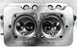

Reconditioning and Exchange of Cylinder HeadsGeneralCylinder heads with worn valve guides, valve seats. or spark plug inserts may be sent to the factory for reconditioning. When the cylinder heads are being reconditioned, the combustion chamber displacement is measured and so indicated in cubic centimeters. Make sure that cylinder heads used in one engine have the same combustion chamber displacement (permissible deviation is +/- 1 cc).
Removing and installing Valve GuidesRemoval
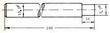
InstallationThe valve guide receiving bores in the cylinder head will have widened somewhat during the removal Consequently. oversized valve guides will have to be used and properly fitted into the head. 1. Precisely measure the valve guide receiving bores in the head. 2. Machine the oversize valve guides on a lathe to bring to outside diameter matching that of the bore in the head. The required preload for the in take and exhaust valve guides is 0.041 - 0.06 mm (0.0016 - 0.0024 in). 3. Press the valve guides into the cylinder head from the rocker arm side. Use tallow for lubrication. 4. Ream the guides with a broach reamer or a precision drill to a diameter of 10 mm E7. If necessary, the valve guides may be reamed with a conventional reamer. Removing and installing Valve Seat Inserts:1. Using a portable electric grinder, grind through a valve seat insert so that it loosens in its seat. 2. Drive the old seat insert out. 3. Precisely measure the seat receiving bore in the head. 4. Machine the oversize valve seat inserts on a lathe to bring to outside diameter matching that of the bore in the head. The required preload is as follows: Intake valve insert: 0.15 - 0.19 mm (0.006 to 0.0075 in) Exhaust valve insert: 0.10 - 0.15 mm (0.004 to 0.006 in) 5. Heat cylinder head to approx. 200 deg C (392 deg F). 6. Using an appropriate driver, drive the valve seat insert into place. 7. Allow the cylinder head to slowly cool to room temperature. Table of Dimensions for Valve Guide Installation(l mm = 0.03937 in)
Table of Dimensions for Valve Seat Insert Installation
|