Clutch R/R
Removal
| - Remove engine and detach from transmission.
- Evenly loosen clutch retaining bolts, slackening each by one or two
turns at a time and switching in a cross sequence until the spring
pressure is relieved, to a void distortion of spring housing.
- Withdraw clutch assembly.
- Withdraw clutch disc,
|
Installation
Installation is accomplished in reversed order of the above by noting
the following points:
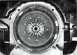
| - Clean clutch contact surface in flywheel and check for wear, If
necessary reface surface and polish with fine polishing cloth. Replace
flywheel if excessively worn.
- Check clutch disc for lining wear, lateral run out, and evenly
working undulated spacers between both lining discs. Devote special
attention to riveted joints securing flange to disc, If necessary,
replace complete clutch disc assembly.
- Check torsion damper for firm seating and inspect springs for
cracks. If in defective condition, replace clutch disc assembly.
- Inspect clutch assembly.
- Check throwout bearing for wear and smooth rotation, replace if
necessary.
- Check control fork seat in transmission housing for wear and good
seating, repair if defective.
- Fill bushing in gland nut at flywheel with approx, 2 cc (.12 cu,
in,) graphite grease or MoS2 compound,
- Install clutch disc with the aid of an arbor or a shortened
transmission input shaft.
- Push clutch assembly onto aligning dowels in flywheel. If the
flywheel is not provided with dowel pins, align clutch assembly with
the help of P 219 locating arbor.
- Evenly tighten clutch retaining bolts, turning each by one or two
turns at a time in a cross sequence to avoid distortion of spring
housing, Use only 10 K hex bolts with lock washers, Torque bolts to
3,5 mkp (25,3 lbs/ft).
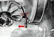
- With transmission attached to the engine pull clutch control lever
in direction of arrow, The distance between the lever and transmission
housing should still be not less than 20 mm (4/5 in,),
|
Last modified: Mon, 17 Jan 2005
Links
|