Removing and Installing Pistons
Special Tools:
P 1a Electric piston heater P 2 Piston pin mandrel
General:
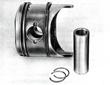
| The piston pins are arranged in the pistons off the center and it is,
therefore, important to correctly install the pistons in the
engine. The piston top bears an arrow mark. When installed, the piston
must be so oriented that the arrow points in the direction of vehicle
travel, i. e., towards the flywheel.
|
| Owing to the off-centered piston pin, the connecting rod shifts its
direction of attack, and so does the piston its tangential angle in
relation to the cylinder wall prior to reaching the top dead center
(TDC). Since in this position the combustion has not yet begun, the
prevailing side forces are still small. which permits the piston to
shift onto the opposite cylinder wall softly rather than with a
slamming impact. As a result, piston slap noise occuring at time of
the pressure point shift is kept at a minimum, especially when the
piston to cylinder wall clearance is greater than normal.
|
Removal
| 1. Remove cylinders (36 En).
2. Mark pistons to ensure reassembly in original position and
location.
|
| 3. Remove piston pin retainers making sure they don't fall into
crankcase.
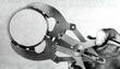
4. Heat pistons to approx 80 deg C (175 deg F) using electric piston
heater.
|
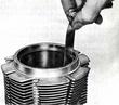
| 5. Using the piston pin mandrel, drive piston pins out and remove
pistons.
6. Remove piston rings (if necessary) using a piston ring expander. To
avoid breaking or bending the piston rings, expane! these as little as
possible, keeping rings close to the piston body.
|
Installation
Install pistons in reversed order of the above by noting the following
points:
| 1. Connecting rods must be in proper alignment.
2. Clean pistons. Remove carbon deposits from piston top and piston
ring grooves without scratching the base metal. Signs of uneven
contact or carbon deposits on one side of the piston may indicate poor
connecting rod alignment.
3. Check piston rings for proper condition, ring gap, and ring groove
clearance. If not as specified, replace piston rings or pistons, as
required.
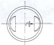
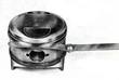
4. Measure pistons. Size designation is stamped into each piston
top. Measurements are accomplished as shown in the illustration
(perpendicular to piston pin axis).
Piston size groups are shown in tables under 40 En. Piston clearance
at installation is 0.02 mm (0.0008 in). If the measurement of the
piston and cylinder reveals a clearance approaching the wear limit,
the piston and cylinder should be replaced with a set falling into the
same size group. If the mating cylinder of a damaged piston does not
show traces of wear or damage, it may be possible to replace the
piston alone with one falling into the appropriate size (letter)
group.
|
| 5. Fit compression rings and oil scraper.
6. Check piston ring gap. This is done by inserting the ring into the
cylinder and pushing it down, somewhat. with a piston. then measuring
gap with a feeler gauge.
Applicable to all rings:
Ring gap 0.3 - 0.45 mm (0.012 - 0.018 in). Stagger piston ring gaps so
that they are approx. 120 deg apart.
Piston ring side clearance is specified in the Table of Tolerances and
Wear Limits (page E 95).
Piston rings must be installed with a ring expander to prevent piston
damage or ring breakage.
Piston rings must be installed in the piston so that the "TOP" marking
on the ring faces up, i. e., towards the piston top.
|
| 7. Insert piston pin retainer on the flywheel side first.
8. Inspect and install piston pin. The piston pin is held in the
piston through interference fit. If the piston pin can be pushed into
the cold piston by hand, use a pin of larger diameter. A color code
marking inside the piston on the piston pin boss indicates the proper
size of the piston pin, as follows:
white - 21. 997 -22. 000 mm
blue - 22.000-22,003 mm
Piston pin clearance in the connecting rod bushing is O. 020 - 0.036
mm (0.OOO8 in to 0.0014 in). If the clearance a pproaches the wear
limit of 0.050 mm (0.002 in), fit a new piston pin into a new
connecting rod bushing.
Install the cold, oiled piston pin in the piston which has been heated
to 80 deg C (175 deg F) through immersion in hot oil or application of
the e1ectric piston heater, in which condition the pin should slide
into the piston under light pressure; the pin should be pushed
through, to the pin retainer, in one continued move.
9. Install second pin retainer. The pin retainers must fit well in
their groove within the piston pin boss.
|
Last modified: Mon, 17 Jan 2005
Links
|