
Generator DescriptionGeneralThe generator has the function of supplying all the current consuming units in the vehicle and to charge the battery satisfactorily. It is driven by the engine by means of a V-belt. To regulate the voltage which varies according to the loading of the generator by the current consumers or by the varying speed of the engine there is a toggle regulator with a sloping characteristic curve. Method of operationThe generator is a DC shunt-wound machine. Its voltage is maintained at approximately the same level by means of a electro-magnetic high speed regulator independently of engine speed and loading. In addition this regulator prevents overloading of the battery. An electro-magnetic switch switches the generator on automatically and at low speeds disconnects it from the battery so that discharge of the battery through the generator is prevented. Regulator and switch are combined to form a regulator switch. In order to protect the generator from overloads resulting from the very high charging current occurring when current consumers are switched on the battery is flat and the voltage constant, regulators with output limitation are used. Variode regulatorThe variode regulator fitted in the vehicle has on the voltage regulator unit a second winding (control winding). This is connected on one side to the switch contact and on the other side via the variode (semiconductor unit) to D+. When current flows through the main current lead a potential drop arises between D+ and the switch contact. When the output limit of the generator is reached the variode becomes conductive as a result of the potential drop. In the, control winding flows a current which strengthens the magnetic field on the voltage regulator unit and thus reduces the generator potential. The generator is thus protected against overload. Construction of generatorThe main components of a generator are: The pole housing with pole shoes and the exciter, winding the armature with armature winding and commutator the carbon brushes and brush holders the bearing cap (drive bearing and commutator bearing) the special regulator switch The pole housing is a hollow cylinder of special iron which forms a very good conductor for the magnetic flux. The pole shoes are fixed on the inside of the housing by means of countersunk bolts into the housing. On the pole shoes are located exciter coils connected in series which consist of a large number of windings of insulated copper wire. Between the pole shoes rotates the armature, an iron core in which are bedded the windings (armature conductors) of the armature coil and on whose shaft is also fitted the commutator (current reversal switch) from which the induced generator potential is collected. The iron core of the armature is made up of a large number of thin stamped out metal plates which are insulated from each other for suppression of eddy currents. The armature coils which consist of a fairly large number of windings of insulated copper wire are located and insulated in the grooves of the armature. The armature conductors are protected against centrifugal throw-out. The total number of all the coils is called the armature winding which consists of as many coils as the commutator has segments, To ensure that all commutator coils are conductively connected to each other and thus always contribute collectively to the production of the generator potential the end of one coil is soldered into one of the commutator segments with the beginning of the next coil. Thus a closed circuit armature winding is effected. The commutator consists of copper segments which are insulated from each other and from the armature shaft. The insulators between the individual segments must be recessed back from the commutator surface so that the carbon brushes will only run on the copper even after a considerable period of operation. The carbon brushes are pressed against the commutator under uniform spring pressure and collect the current produced in the armature coils. The carbon brushes locate in box shaped brush holders. The armature shaft is mounted in ball bearings on both sides. Both the bearing caps, that of the drive bearing and the commutator bearing seal off the pole housing from outside. The commutator bearing is covered by a cover strip so that the generator will be easily accessible for servicing of the carbon brushes and the commutator. Maintenance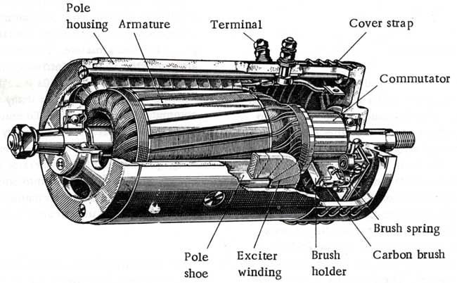 The ball bearings in the generator are packed with ball bearing grease (e. g. Bosch FT IV 33) and normally require no attention. Repacking with grease, which under no circumstances should be done with normal lubricating grease, will normally only take place during the course of an engine overhaul. 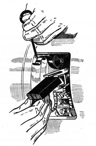 Approximately every 10,000 km (6000 miles) the cover strap should be opened and the carbon brushes checked for wear and free travel. Used brushes should be replaced. The carbon brushes should not be oiled. |

