912 Manual Replace Cooling Blower
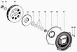
Parts List
|
Parts diagram of the fan and associated plates.
|
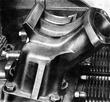
Remove and Installing Cooling Blower
The detachable generator carrier permits withdrawal of the generator
and blower impeller assembly without removal of the entire air blower
housing. The work procedure is as follows:
Removal
|
Remove the strap and bolts holding the fan to the shroud.
|
|
Remove the generator from the stand.
|
Installation
The installation is accomplished in reversed order of the above by noting the following points:
- Properly connect generator cables (brown cable to Terminal D-,
black cable to Terminal DF, red cable to Terminal D+).
- Insert new gasket between the generator carrier and timing gear cover.
- Check for proper V-belt alignment between the generator and
crankshaft pulleys and correct be repositioning the generator in its
cradle; however, make certain that no tension is created between the
blower housing cover and the blower housing when the retaining screws
are tightened.
Removal and Installation of the Cooling Blower Fan
Special Tools
P 42 Torque wrench, or
VW 118 Torque wrench
P 44 Hex socket. 36 mm, for P 42,
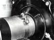
Removal
|
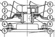
Diagram of the fan installation to the generator shaft.
- Remove air blower.
- Mount generator in a vice by fastening it by the pulley spindle
through plastic or aluminum grip protectors.
- Unscrew the special impeller nut and withdraw impeller together with its back shield.
|
Installation
- Note the proper arrangement of spacers.
- Position impeller shield.
- Tighten the special impeller nut to 10 mkp (72. 3 lbs/ft).
- The clearance between the blower housing cover and impeller should
be approximately 3 mm (1/8 in.).
- When turning, the impeller should not strike the housing cover.
|