Flywheel R/R
Special Tools:
P 44 Hex socket (36 mm)
General
The flywheel is attached to the crankshaft by way of a gland nut;
eight dowel pins transmit the torque forces. A soft iron gasket is
installed between the flywheel and the crankshaft. Oil sealing is
accomplished by an oil seal installed in the crankcase at Bearing 1;
the seal rides on the flywheel hub. The gland nut contains a - pilot
bushing which supports one end of the transmission input shaft.
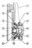
| - Flywheel
- Oil seal
- Spacer
- G land nut
- Gasket
- Spring washer
- Crankcase
- Bearing 1
- Crankshaft
- Pilot bushing
- Oil gallery
- Dowel pin
- Soft iron gasket
|
Removal
- Remove clutch pressure plate.
- Withdraw clutch plate,
- Remove gland nut using P 44 hex socket,
- Withdraw flywheel.
Installation
Installation is accomplished in reversed order of the above by noting
the following points:
| - Inspect flywheel starter ring for serviceable condition of gear teeth; slightly pounded teeth may be dressed with a file.
- Check dowel pin seats in flywheel; if the seats appear peened, install a new flywheel.
- Check dowel pins in the crankshaft, replace if necessary.
- Use new soft iron gasket,
- Check and adjust crankshaft end play.
- Check pilot bushing in gland nut for wear.
- If the pilot bushing requires replacement, install new needle
bearing with gland nut.
- Torque gland nut to 45-50 mkp (326-362 lbs/ft).
- Check flywheel for runout. Maximum lateral runout is 0.3 mm (0.012
in), measured in the middle of the clutch plate contact area. Maximum
vertical runout is 0,1 mm (0.004 in). Note specifications in the table of
tolerances.
|
Note:
| Crankshaft and flywheel are balanced as a unit and always marked with
a number. It should be noted at time of installation that both
identifying numbers are same. Replacement flywheels or crankshafts are
balanced to 0 so that they are individually relaceable,
To ensure proper installation of the flywheel in relation to the
crankshaft, two dowel pins have been positioned closer together; this
point is identified on the crankshaft and flywheel by the number 1
stamped into both parts.
|
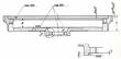
Reconditioning Flywheel
If necessary recondition the flywheel gradually on a lathe (according
to table below). Please pay attention to the fact that the bearing
surface of the clutch must be reconditioned by the same proportion as
the thrust surface of the flywheel.
|
| Measuring point | Original measure (mm) | Grade 1 | Grade 2 | Grade 3 | Tolerance |
| A | 12.3 | 11.8 | 11.5 | 11.2 | +/- 0.1 |
| B | 22.5 | - | - | - | +/- 0.2 |
| C | 39.5 | 38.8 | 38.4 | 38.0 | +/- 0.2 |
| D | 13.25 | 12.95 | 12.75 | 12.55 | +/- 0.1 |
| E | 3.15 | 3.1 | - | - | +/- 0.05 |
| r | 0.5 | 0.5 | - | - | - 0.2 |
| b | 1 deg 30' | - | - | - | - |
|
Last modified: Mon, 17 Jan 2005
Links
|