R/R Cylinder Head
Special Tools
- VW 157 Allen wrench adapter
- VW 118 Torque wrench
Removal
This section assumes the engine is removed.
| - 1. Remove lower air duct, side shield, cylinder shrouds, intake duct
and carburetor.
|
| - 2. Remove rocker box cover and unbolt rocker arm carrier.
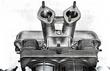
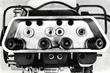
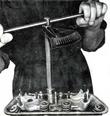
- 3. Remove cylinder head retaining nuts with A Allen wrench adapter
(the 8 A Allen nuts are shown above and below the valve stems in the
illustration above); remove washers located between the nuts and
cylinder head.
- 4. Withdraw cylinder head.
|
Installation
Installation is accomplished in reversed order of the above by noting
the following points:
- 1. No gasket is used between the cylinder head and cylinders.
- 2. Insert push rod cover tubes. To ensure proper sealing at the tube
ends between crankcase and cylinder head. the tubes must have the
required length at assembly, that is, used tubes must be stretched at
the bellows. The stretching should be accomplished with care so as to
prevent possible cracking of the metal.
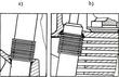
| - 3. When installing the cylinder head make sure that the new a-rings at
the cover tube ends are properly seated; position the tubes weld seams
up.
- a) Sealing points in crankcase.
- b) Sealing points in cylinder head.
|
| - 4. The cover tube O-rings are trapezoidal in cross-section.
- 5. Prior to installation, lubricate 0 -rings used under the cylinder
head nuts located within the rocker box.
- 6. O-rings should not be coated with gasket compound.
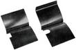
- 7. Ensure proper positioning of cylinder deflector baffles (compare
profile of recess for cap nut and one for hex bolt).
|
| - 8. Place 1 washer under each cylinder head nut situated outside the
rocker box.
|

| - 9. Coat cylinder head nuts with graphite paste tighten lightly. then
torque to 1 mkp (7. 2 lbs/ ft) in sequence shown in the illustration.
- 10. Torque cylinder head nuts to 3 mkp (21.7 lbs/ft) in sequence
shown in the illustration.
|
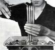
| - 11. Pump oil into pushrods until it comes through at other end, and
insert into pushrod cover tubes so that one end seats in the valve
lifter.
|
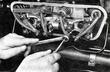
| - 12. Install rocker arm carrier, torque retaining bolts to 5 mkp
(36.2 lbs/ft).
- 13. Install rocker arms.
- 14. Torque rocker arm shaft retaining nuts (SW 13 mm) to 2.5 mkp
(18.1 lbs/ft).
|
| - 15. Adjust valve clearance.
- 16. Mount rocker box cover.
|
Note
When installing the cylinder head make absolutely sure that the
cylinders are properly seated in the cylinder head. If a misaligned
cylinder head is tightened, it will most likely warp to the extent
of being no longer useable.
|