Camshaft R/R
Removal
- Disassemble crankcase (41 En).
- Withdraw camshaft.
Installation
Install camshaft by noting the following points:
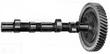
| - 1, Check for firm attachment of camshaft gear to camshaft.
- 2. Check camshaft for wear at bearing journals and camshaft lobes,
i.e., rippled wear in lift ramps or slanted wear, in relation to
camshaft axis, or cam lobe races, End play specifications are shown in
the table of tolerances.
|
| - 3. Check camshaft for whip.
- 4. Check camshaft gear for good condition and proper tooth contact.
- 5. When installed, the camshaft gear tooth marked "0" lies between
two crankshaft gear teeth bearing a punch mark each.
|
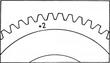
| - 6. Check gear backlash over the entire circumference of the camshaft
gear. Correct backlash, in assembled crankcase, between the camshaft
gear and crankshaft gear is 0,015 - 0,04 mm (0.0006 - 0.0016 in). To
measure, move gears back and forth while taking readings with a dial
gauge and measuring the entire circumference of the camshaft gear,
To facilitate proper backlash adjustment, camshafts are furnished
with camshaft gears in five sizes.
The camshaft gears are marked on the camshaft side with electrically
inscribed or mechanically stamped identifica don num bers such as 0,
+1, +2, -1, and -2, The numbers show, in hundreds of one millimeter,
by how much the pitch circle radius differs from standard size (0); it
identifies a standard gear 0, oversize of +1 or +2 (+ 1/100 or +2/100
mm), or undersize -gears.
Note:
Do not confuse the number "0" with the timing mark "o" on the other
side of the gear. The crankshaft gear is supplied in one size only and
no identifica tion is necessary .
- 7. Lubricate camshaft with graphite oil and install.
- 8. Do not fail to install camshaft end plug.
- 9. When assembling a new crankcase, check camshaft for snug but easy
rotation; if necessary check camshaft bearings with machinist's
blue and smoothen bearing seats in crankcase with a scraper.
Note:
When installing a new camshaft gear ensure that the timing mark on the
camshaft gear, its nearest mounting bolt bore, and the oil pump drive
slot on the camshaft end align in an almost straight line.
Before drilling the 5,8 mm ( 0.228 in) dowel pin holes, and tapering
these from the camshaft side, check the gear for runout, The three
dowel pins must be firmly seated in the camshaft gear and additionally
secured by three punch strikes each. If necessary, install larger
dowel pins which may be locally manufactured from high-grade
steel. Torque retaining bolts to 2,5 mkp (18 lbs/ft).
|
Last modified: Mon, 17 Jan 2005
Links
|