Description of the Solex 40 P II - 4 Carburetor
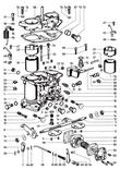
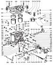
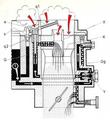
Parts Diagram
|
This diagram is for the early cars.
|
|
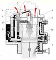
Later cars.
|
General
| The Type 912 Porsche is equipped with two SOLEX 40 P II - 4
double-throat downdraft carburetors. The induction throats are 40 mm
(1.575in) in diameter. Since the carburetors are located very close to
the combustion chambers, cold starting enrichment devices are not
needed.
|
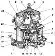
Description
| The carburetor basically consists of the main body and cover, with a
gasket separating the two. The main body contains two induction
barrels, each having an independent idle and power metering
system. The throttle shaft, which passes through both barrels,
controls both throttle valves and carries a throttle return stop and
throttle arm.
|
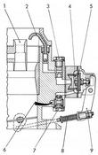
| The accelerating pump located on the broad side of the carburetor is
actuated through an adjustable rod and feeds fuel to both induction
throats.
|
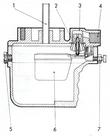
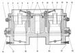
| The float chamber is located between both induction throats. The
fuel level in the float chamber is regulated through the buoyancy
of the float, that is, the float tang opens or closes the float needle
valve. The float level may be adjusted by means of an externally
located screw which adjusts the height of the intermediate swivel
joint. This provision makes it possible to easily adjust the float
level for the particular grade of fuel used. The fuel level may be
checked by removing the plug from the inspection port.
The carburetor cover accommodates the fuel inlet, float chamber vent,
and float needle valve (the latter is accessible from within). In
addition, two power enrichment nozzles are press-fit into the cover.
|
Idle Metering
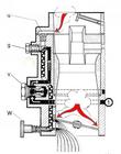
| The fuel enters through the idle metering jet (g) and mixes with air
entering through the idle air bleed (u) forming an emulsion. The
emulsion flows to four small discharge ports located near the throttle
valve. The amount of emulsion dispensed through the lowest port is
controlled by the idle mixture screw (W). The emulsion dispensed into
the induction throat through the idle mixture port combines with
induction air which is passing through the partly open throttle valve
and atomizes into idle mixture.
The idle mixture can be leaned out by turning the adjustment screw in,
and enriched by turning it out: both screws should be set
approximately same.
The idle speed adjustment controls the engine idle rpm, i. e.. turning
the screw clockwise increases the rpm, and turning it counterclockwise
decreases rpm.
The idle system employed in this carburetor is an independent system
since it draws the fuel from a point before the main jet carrier
(Y). As a result, negative pressures prevailing in the induction
throat have a continuous effect on the idle metering system and a
certain amount of the idle mixture is fed into the induction throats
at normal power settings as well.
|
Intermediate Metering
| The three discharge ports located above the idle mixture discharge
port provide progressive metering at intermediate throttle openings
between idling and power. The lowest port, located at the throttle
valve level, feeds idle mixture when the throttle is set for idling,
while the two upper ports begin to feed the mixture as the throttle
begins to open. This metering provision ensures smooth transition from
idle speeds to power settings.
|
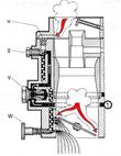
Power Metering
| The fuel flows through the main jet carrier (Y) and the main jet (Gg)
into a well which contains the emulsion tube (s) and, directly above
it, the air correction jet (a). Vacuum in the induction throat draws
the fuel into the preatomizer (X) where it mixes with air and
continues to the venturi (K) where it is fully atomized into the
combustion mixture. As the vacuum in the induction throat increases,
the fuel level in the emulsion tube well decreases and air enters
through the air correction jet, mixing with the fuel through orifices
in the emulsion tube and effecting a derichment of the fuel air
mixture.
|
| As long as the engine is operating in the mid-rpm range under partial
or full throttle load, only the main metering system supplies the
fuel. However, as the air velocity in. the induction throat increases
with increasing rpm, the vacuum effect in the throat becomes so
intense that it begins to draw supplemental fuel from the power
enrichment nozzle (q1); the power enrichment system consists of the
discharge nozzle ([1) and the metering jet (q2) and draws fuel
directly from the float chamber. The enrichment system comes into
action when the engine is running under full throttle at high rpm.
The main metering system together with its supplemental enrichment
system ensures a well balanced and metered fuel! air mixture required
for combustion, realizing the desired fuel economy and, yet, maximum
power output on demand.
|
Acceleration
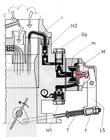
| A mechanically actuated diaphragm-type accelerating pump is
employed. The pump receives fuel directly from the float chamber. When
the pump is at rest,. the diaphragm (M) is kept outwards by the
diaphragm spring (m). A s the throttle valve opens, actuating motion
is transmitted to the pump by the pump rod (T) and pump lever (L5),
pushing the diaphragm inward against the fuel and forcing it to pass
through the pump jet (Gp) and the calibrated injection nozzle (i) into
the venturi, enriching the fuel/ air mixture and resulting in smooth
engine response at acceleration.
The check valve (Hl), in the pump inlet, prevents the fuel from
backing up into the float chamber; a second check valve (HZ), at the
base of the injection nozzle, prevents air from entering the pump
through the injection nozzle when the pump is on the inlet stroke.
The amount of fuel dispensed by the pump on its pressure stroke at
time of acceleration is predetermined by the length of the pump
stroke; the stroke can be adjusted through the pump adjustment
(t). The pump jet and the calibrated injection nozzle control only the
duration of injection.
|
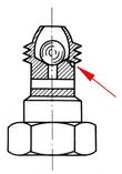
| The check valve assembly (HI) has a return flow passage measuring
O.36 mm (0.0142 in) in diameter. This port prevents excessive
enrichment of the fuel/ air mixture by fuel dispensed by the fuel pump
during acceleration, that is, depending upon the speed with which the
throttle pedal is depressed, larger or smaller amounts of fuel are
permitted to flow back to the pump.
|
Last modified: Fri, 12 Aug 2005
Links
|