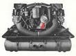
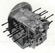
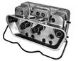
| The engine shown is for a 1965-1966 SWB car and has the German heating
system. There is no smog equipment on the car other than crank case
ventilation from the oil filler can to the right hand head.
In late 1966 the motor mount changed from the flat plate shown to a
U-shaped channel with 4 rubber motor mounts. ...More
|
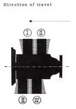
| Here we see a diagram of the engine showing how the cylinders are
numbered. One additional piece of information is the cylinder firing
order:
1-4-3-2
...More
|
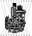
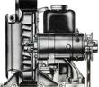
| The figure shows a cutaway view of the engine with major items identified.
...More
|
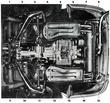
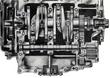
| The bottom view again shows the German edition of the 912 with
different heater components including modified heat exchangers and
muffler. This version was used for Sweden and Germany. The rest of
the world recieved 'flapper boxes' patterned after the VW Beetle of
the period. Notice also that the mounting system for the exhaust
system is different with what appears to be connections to the third
piece of the engine case.
...More
|
| We often refer to the timing gear cover as the 'third piece'. The
manual description is interesting because there it includes assembly
instructions which seem out of place in this section of the manual.
...More
|
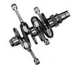
| Here we see the crankshaft and connecting rods.
The four connecting rods ride on the plain-bearing crankshaft in
lead-bronze bearing inserts. All connecting rods have bronze piston
pin bushings. All crankshaft journals are soft nitrided.
...More
|
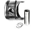
| The light-alloy pistons in the Type 912 engine have 3 piston rings
each, the lowest ring being the oil scraper. The piston pins float in
the connecting rod bushings; they are contained within the pistons
through the use of circlips.
|
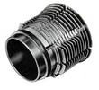
| A big bore kit has larger diameter pistons, from 83.5mm to 86mm. The
cylinder description is, of course, for the stock cylinder which are
not suitable to be bored out to accept the larger diameter
pistons. Cast iron cylinders used for the 356C engines are often used
for this purpose.
...More
|
| The clylinder heads are symetrical left and right. The combustion
chamber needs to be modified for the narrower sealing surface of big
bore cylinders.
...More
|
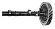
| The 3-journal camshaft rides on the base metal of the
crankcase. Camshaft drive is through helical gears; the timing gear is
of light alloy. Valve timing is effected through cams, valve lifters,
push rods, and rocker arms. Each cam alternately actuates one valve of
two opposing cylinders. The exhaust valves are cased with high-grade
chrome-nickel steel.
...More
|
| The engine is cooled by an air blower. The blower impeller is situated
on the extended generator shaft which is driven by the crankshaft over
a V-belt. The blower draws cooling air through an intake in the blower
housing and forces it over the heavily finned cylinders and cylinders
heads. The cooling air is guided by deflector baffles.
|
| The engine oil supply is in the bottom of the case, normal with wet
sump lubrication systems and unlike the 911.
Engine lubrication is effected through a forced feed system and
includes an oil cooling provision.
...More
|
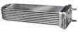
| The stock oil cooler is made of steel and is associated with cracks in
the case. An aluminum replacement is available which has better head
transfer characteristicsand is lighter weight, putting less stress on
the case.
The oil cooler is mounted on the crankcase in the stream of cooling
air forced through by the cooling blower. The oil cooler is so
inserted into the oil circuit that the oil pumped by the oil pump must
pass through the oil cooler before it reaches the points of
lubrication.
...More
|
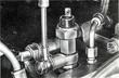
| There are two electrical sending units shown in the diagram. The
vertical one is the pressure sender and the horizontal one behind it
is the temperature sender. It is not uncommon for these to fail and to
leak oil.
...More
|