Connecting Rods R/R
Special Tools
VW 310a Crankshaft bench mount
Removal
- Remove crankshaft and place into VW 310a bench mount (50 En).
- Remove connecting rod retaining nuts, remove connecting rods and caps.
Installation
Installation is accomplished in reversed order of the above by noting
the following points:
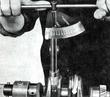
| - 1. Check connecting rod weight: Maximum permissible weight difference
between connecting rods of one engine is 6 g ( 0.211 oz.).
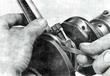
- 2. Check piston pin bushing. The piston pin should enter a new bushing
under light finger pressure.
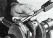
- 3. Check connecting rod alignment and correct if necessary.
- 4. Upon thorough cleaning of all parts install connecting rod inserts
and assemble connecting rods. The identification number stamped into
the side of the connecting rod and its bearing cap should be on the
same side when assembled.
- 5. Torque connecting rod retaining nuts to 4.5 mkp (32.5 lbs/ft).
|
| - 6. Visually check if connecting rod and its bearing cap have actually
joined, that is, if no obstruction is in the joint.
- 7. Minor stresses which may result from tightening the connecting rod
retaining nuts can be relieved through light hammer blows. The
connecting rods, oiled prior to installation, should tip freely
under their own weight. Under no circumstances may bearings be dressed
or reworked to fit.
|
| - 8. Check lateral clearance between connecting rods and crankshaft
(0.15-0.20 mm) (0.006 to 0.008 in).
|
Last modified: Mon, 17 Jan 2005
Links
|