|
Steering Shaft Remove and Replace
Introduction
I have been chasing a problem with a slight tracking problem at
highway speeds. This ghost has led me to explore many things about
the steering and suspension, most of which were useful improvements
but most have not affected the wander. This note describes how to
remove and replace the steering shaft universal joints.
Note: The steering shaft and extension post have changed in
design over the years. The early cars are similar to mine but changes
were made which make these procedures and parts design different in
detail. In particular, the universal joints shown are no longer
available from Porsche, having been superseded with newer designs that
are not compatible with the earlier cars. The new universal joints
have spines that do not match the splines on the shafts. As a result,
all three of the shafts must and both universals must be replaced
upgraded if you elect to use new parts. The old universal joints do
not have any splines - they were smooth!
Beginning with VIN numbers 305 101('67 911), 354 001 ('67 912) and
458-101 ('67 912 Karmann), internally splined universal joints were
introduced. The steering upper shaft, intermediate shaft and lower
shafts were provided with splines which mate with those in the
universal joints. The splined shafts and universal joints are not
interchangeable with universal joints without splines. When
installing internally splined universal joints, both universals and
all 3 matching shafts have to be installed.
The Steering Shaft
Here is a picture of the original design intermediate steering shaft.
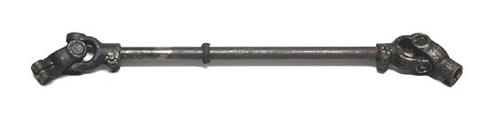
The shaft and two universal joints shown are used, purchased from
Parts Heaven in Hayward, CA for $25.
To gain access to both universal joints, the steering post extension
with the light switches must be removed. This is a bit ugly if you
have a steering lock. I will describe what the factory manual has to
say about that problem, but my '66 model does not have a steering
lock. If it did, I probably would have been satisfied with changing
only the lower universal.
Removal
| - Disconnect the battery. You'll be messing with wiring under the
dash and removing the steering wheel and may be moving pieces of the
auxiliary gasoline heater.
- Remove the carpeting in the front compartment. Open the access
door to the auxiliary heater. My car does not have such a heater, so
the procedure is simpler.
- If you have a heater, detach the auxiliary heater duct from the
steering post and bend the duct to the side.
- Remove the intermediate shaft cover. You'll have to remove the two
spring clips holding this cover. The manual recommends prying up one
of the two prongs in the spring clip using a small screwdriver. I
managed with a pair of pliers on the clip.
- Again if you have a heater, remove the heater pump retaining
bolts and lay the pump to the side.
- Remove the cotter key from the lower clamping bolt in each of the
two universal joints and remove the bolts.
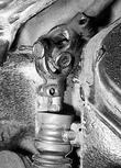
- Remove the retaining Allen bolts from the bushing cap on the lower
steering shaft and remove the cap. See the picture above.
- Pull the universal joint off the steering lower shaft. IMPORTANT:
this job is much easier if you spread the clamp by twisting a large
screwdriver in the slot.
|
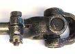
| - Pull the intermediate shaft out of the lower part of the upper
universal joint. You may have to spread the clamp slightly to allow
the dowel pin enough room to slide through the slot. The picture shows
the dowel pin.
- The intermediate shaft and one universal should now be free.
- You must now remove the steering column and switch assembly to
access the other universal joint. If you are only interested in the
universal joints as we were, both joints can now be inspected. Proceed
with the rest of the process as required by your situation.
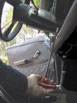
- Remove the steering wheel.
- The following applies if you have a steering lock. Remove
steering lock cover, drill shearing bolts out, and remove steering
lock with safetying spacer (do not disconnect electrical cables).
- Using special tool P281, remove light switch and let hang on
wires.
|
| - Remove Allen bolt in switch assembly retaining clamp. This clamp is
found under the steering column on the right side near the dash.
- Rotate the clamp until the locking pin is visible. It is left of
center on the bottom of the steering column. Pull the locking pin out
with pliers.
- Disconnect cables leading to the switch assembly by detaching the
plug-in connectors and various crimp on single wire connectors. You'll
have to replace all of these, so write down where they all go. On my
car it is pretty obvious by following the color coding. The cable
length and connector design determine where the multi-pin connectors
go, but I did number these as I removed them.
- Withdraw the switch assembly including the steering upper shaft
and the universal joint, at the same time guiding the electrical
cables through the space on the instrument panel. Don't forget to
disconnect the ground wire that you didn't notice the first time which
goes off to the right.
|
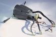
| - With the steering post out of the car you have access to the upper
universal joint.
- If there is any play in the universal joints replace them. I had a
choice of four universal joints and selected the two that were
perfectly tight to use. Were the original universal joints loose
enough to cause my tracking problem at high way speeds? Not entirely.
|
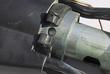
| - Here is a close up portion of the picture above showing the
steering post showing the hole where the locking pin fits. The inner
surface of the clamp has a groove that captures the locking pin so
that the entire assembly is secure. Also of interest is the hole in
the side of the post where the steering lock would fit.
|
Replacement
- Treat the large plastic grommet for the steering post and the
joining end of the post with silicone lubricant. I have a tube of
this material left over from replacing the spring plate bushings. Push the post into place.
- Before installing the steering column cross check the distance from
the top surface of the steering column and the outer flared tube
containing the steering shaft. This tube should be 7 mm recessed from
the front surface of the column. There is an inner section of that is
clamped by the two hex head screws on the bottom of the column, either
side of center line.
- I did not take the upper shaft out of the steering column because I
was just interested in the universal joints. There is a snap ring that
must be removed to start the process.
|