Steering Switch Assembly
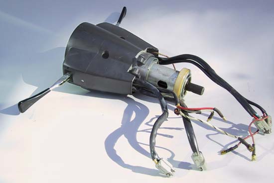
- This is a bottom view of the switch assembly which shows the clamping joint.
- The universal joint attaches directly to the shaft on the right
side of the picture.
- Also visible are the two holes to the left of the clamping joint
that provide access to the Allen retaining bolts which secures the
steering post extension.
|