
912 IgnitionImprovementsHere's what I've done to the ignition system:
Aside from that, everything is original :^). Note:See the new description for timing the engine with a timing light at the bottom of this page. Distributor AdvanceThe owners manual recommends timing at 3 deg. before top dead center (BTDC). Pertronix instructions suggest 5 deg BTDC. Duane Spenser recommends 28-32 deg advance at 3000 RPM. What is going on here? The answer lies in your distributor. The distributor is mechanically advanced with a vacuum retard on later cars. The mechanical advance is operated by centrifugal force. The faster the engine the more force the more advance. However, there are some limits. At low RPM there is a range that occurs before there is enough centrifugal force to start the advance curve. At high RPM the advance mechanism reaches a mechanical limit preventing further advance. The factory engine manual includes an advance curve graph for the distributor which has degrees on one axis and distributor shaft speed on the other. Remembering that the distributor shaft runs at half the speed on the engine (so that the cylinder will fire on every other rotation) we can pick some points on the curve. There are two curves on the graph. The distributor advances until the it reaches some stops then flattens out. The graph is for the 022 distributor which was original equipment on the '66 cars like mine. The two curves show the range of acceptable advance, probably based on production tolerances, spring rates and wear. The table is showing engine RPM vs advance on a distributor test machine. The actual advance will be an additional 3 degrees, the distributor is rotated by that amount per spec unlike the data from the test machine. This data is from a distributor test machine, not from the car.
Note:
The point to all this is that the actual advance is a function of the engine RPM. Higher RPM, more advance. Since we can not readily adjust the advance curve it is best to set the maximum advance - near operational RPM rather than at idle. Modern engines control the advance electronically based in part on information from the oxygen sensor to determine optimum burning of the fuel. Pertronix Ignition
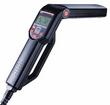
First Tune-UpI first had my car tuned by Harry Pellow at HCP Research. Several of his books provide recommendations that match pretty well with other printed material on how to tune the car. I bought a timing light from Sears. After using this one for a couple of years I have upgraded to to a Digital Timing Light. See the bottom of the page for details. There are no marks on the engine pulley except for top dead center (TDC). Correct timing is critical. The car now starts and runs well. Cylinder DefinitionThis diagram is from the factory 912 engine manual. The arrow on the diagram shows the direction of travel.
Firing OrderThe owners manual defines the firing order as 1-4-3-2. Set TDC for Cylinder 1The crankshaft rotates twice for each revolution of the distributor. Top Dead Center (TDC) is marked with a small line on the rear edge (away from the engine - toward the rear of the car) of the crankshaft pulley. Mark this line with some white paint for good visibility. The distributor shaft has a tab that fits into a slot in the engine for drive. The slot is off center which determines how the distributor meshes into the engine on installation. The factory manual specifies:
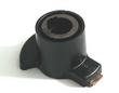
Distributor DifferencesThe alignment of the 'central slot' described above is not the same for the 022 and the 050 distributor. That for the 050 is rotated about 60 degrees clockwise compared to the 022. This means that the spark plug wires from the right side of the engine are nearer to the rear of the car into the distributor cap and those from the left side are nearer to the front. The 022 installation is more symmetrical, with the left side entering the left side of the cap. If you have the 009 distributor, take it out and throw it away. The 'advance curve' describes the way the distributor controls the timing at running speeds. The 009 advance curve was designed for a VW beetle and is not aggressive enough for the 912 engine. Buy the 050. Spark PlugsThe old ones were labeled Bosch W225T1. The new ones are Bosch W5AC. These are copper electrode plugs. Luckily I have a spark plug removal tool left over from an old Porsche, probably the 944 which works well for removal and installation of the plugs. The rear ones are just behind the carburetors and are painful to remove and install. Ignition WiresThe new ignition wires do not have a final rubber sleeve over the end of the plug end insulator. Since this is a fair weather car, I did not try to rescue those left on the old insulators. The wires were numbered, but not in cylinder order as shown above. I moved the number tags to match the cylinders. Static TimingThe firing point is 3 degrees before top dead center (BTDC); this is equivalent to approximately 3.6 mm (9/64 in.) on the pulley rim. Turn the crankshaft clockwise until the distributor rotor points to a small notch in the distributor housing and, at the same time, the "OT" mark is 3.6 mm to the left of the vertical make on the crankcase housing below the generator support. Static Timing ProcedureThis is the information from the factory manual. I don't recommend it. Instead use a timing light. This procedure could be used when you are getting the car started for the first time after installing a new distributor.
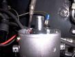
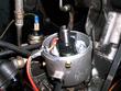
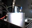
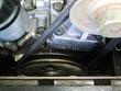
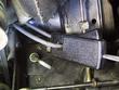
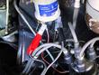
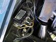
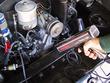
ResultsWow! Now the car starts easily and revs to above 5000 RPM, pulling strongly in all gears. It might even be generating close to 100 HP... Well maybe not, but I'm happy with the result. Dynamic TimingIf you get the recommended Sears timing light (the one with the knob on it that you can use to set the dwell angle) this procedure is very easy. This description is pretty elementary, so forgive me if I seem to be talking down to you. Timing lights flash a strobe light when triggered. The light illuminates a mark on the engine pulley. The trigger is supplied by the pulse from a spark plug wire. We use the number one cylinder to make the measurement. The trigger sensor on the Sears unit uses induction with a little clamp on a pickup. Power to the light is supplied by connecting to 12 volts. More description detail is available by clicking on the picture to see a larger view. Pictures
Update - February 2003
Links
Site Details.
Disclaimer.
Comments? Questions?
Dave Hillman
Content attribted to others remains their property. Otherwise the text and images are licensed under a Creative Commons License. 

|