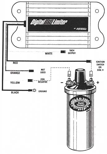
Pertronix Rev Limiter Connection Digram

Here we see the connection diagram included in the Digital Rev Limiter
documentation.
- Attach the BLACK wire to a good engine ground. Make sure to
remove any dirt or paint beforehand. We used the ground point next to
the voltage regulator.
- Attach the RED wire to a 12 volt power source controlled by
the ignition switch. We are using the wire to the coil.
- Attach the YELLOW wire to the coil's negative terminal.
- The ORANGE wire is not used.
- The WHITE wire is a tachometer output but is incompatible
with the 912 tachometer according to my tests.
|


