|
Heater Adjustment
12/3/00. Updated 1/13/02.
I adjusted the heater today. Now that the weather has cooled off I am
starting to rely on the notorious Old Porsche Heater which did not work
well on my first 912 and I do not expect to work well on this one.
But wait a minute! Does it work as well as it could? Is is correctly
adjusted? Well, I first looked at the factory manual which points out
that system is the same as the the 356B/T6 heater and to look at that
documentation. It then concentrates on remove and replacement of the
heater cables and adjustment of the handle friction. Not much help.
The cables from the heater control in front of the transmission shift
lever attach to a pair of air gates, one on each side of the engine.
These can be readily seen by removing the rear wheels and viewing the
duct work coming from the heat exchangers on the engine that terminate
at these valves. The system is simple. With the control all the way
forward the gate valves should be open. When the control is back the
valves should be closed.
This is a simple adjustment, although I made some non-standard choices
on the way in order to make the controls work a bit more freely. See the
discussion with the pictures to understand what I am saying here.
The manual discusses the control handle and its friction plates that
insure the control stays where you leave it. I do not have a problem in
this regard, so this note is purely about the gate valves.
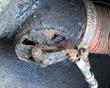
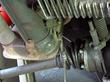
| Dirty isn't it! The heater control is at full heat for this picture.
Clearly the valve is out of adjustment. In this position the gate valve
should be closed, but you can see it is still partially open. To readjust
the lever needs to be rotated on its shaft. The first step is to remove
the cable and lever arm. Then clean off the dirt. The gate valve has a
spring that forces it toward the open position. This spring works fine
on both sides for my car. See the full size pictures for more detail on
the process.
|
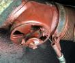
| Same view as above after cleaning, a quick spray with primer and
reassembly. Reassemble with the heater in the off position which
provides the maximum length cable. Position the lever arm at the end of
the cable in order to have the maximum rotation when pulling the cable
as the heater is turned on. Note: I turned the lever upside down in
order to match better with the cable opening at maximum heat. The factory
pictures show this lever the other side up.
|
| The description below refers to my 1966 heater. Looking at pictures of
later engines suggest heat exchangers were used in later years.
The heater control also controls the flapper valves on the heater
boxes below the cylinders on the engine. You can adjust these such
that they close with the gate valves shown above. There are two
flappers, one at the rear and a second that makes a box when they are
closed.
This flapper valve arraignment is one of two heater designs and was
the one exported to the U.S. and most other parts of the world.
When these flappers are open, hot air gets dumped down and out of the
engine. When closed the box gets pressurised and hot air is forced to
the gate valves. Air is forced past the cylinders and forced to the
passenger compartment. There is no heat exchanger. This system is
known as the 'Export Model' heater.
The other design is more like the 911 and was used in Germany and
Sweden. Hot engine air goes into a heat exchanger and exhausted. Cool
air is bled from the fan side of the engine and forced through the
other side of the heat exchanger and to the passenger compartment.
If your car leaks oil into the cylinder area, oil smell will get into
the passenger compartment with the Export model. The alternate design
prevents this. I suspect there may also be a problem with carbon
monoxide if the exhaust manifold leaks with this design. As a result,
good maintenance is important in this area.
|
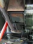
| Adjusting the flappers seems to work best if the heater control is set
to maximum heat - control all the way to the rear. There are wire
controls just like the gate valves that are attached to a bell crank
with a small bolt that has a hole in it for the wire to pass through.
The control wire is at its shortest position when the heater is set to
ON. You can close the flappers manually by pushing the rear most
toward the front. The inner one should close in synchronization. It
is easiest to take the bolt out, thread the wire on it and replace the
bolt. The wire hole in the bolt is next to the bolt head. There is a
small washer between th wire and the bell crank.
This picture shows the bell crank in the closed position.
|
Last modified: Sun, 13 Jan 2002
Links
|