
Engine Starter DescriptionGeneral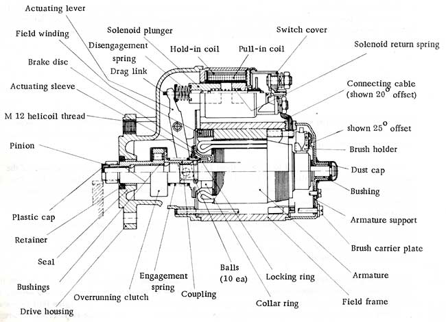 The purpose of the starter is to start the engine, Type 911 and 912 cars are equipped with a starter of 0,8 HP rating, designed for 12 V systems. The starter has a helical spline drive with a self-releasing pinion (BOSCH Type EB). As in most cases, the starter is a DC motor. It provides a considerable amount of torque needed for turning the crankshaft at speeds needed for starting the engine and with enough force to overcome the initial resistance on the compression stroke. To obtain the necessary torque from a starter and battery of proportionately acceptable size, the starter drives the starter ring on the flywheel with a small pinion. The gear teeth in the starter ring and starter pinion are beveled on one side to make engagement smoother, 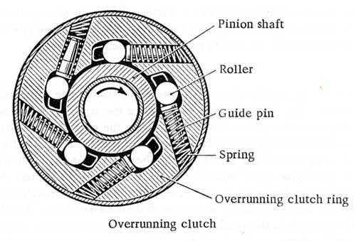 Due to the high gear reduction ratio between the starter ring and pinion, the pinion cannot remain engaged with the starter ring longer than necessary since the armature would be forced to spin at excessively high revolutions. Therefore, the connection between the armature and starter ring must be automatically interrupted as soon as the engine has fired up. In the BOSCH helical spline starters the interruption is accomplished by means of an overrunning clutch situated between the pinion and armature. The clutch breaks the connection as soon as the engine speed becomes higher than that of the starter. A coupling, which rides on the helical spline shaft of the armature, is connected with the pinion through the overrunning clutch. Located on the coupling is an actuating sleeve which can slide back and forth. A fork-shaped end of the actuating lever is constantly engaged in the actuating sleeve. The actuating lever moves the locking ring forward. Balls located in the coupling bores are freed and the pinion is free to move towards the engagement phase. When moving forward, the pinion rotates on the helical splines. The application of thrust and rotation prompted the designation as helical spline starter. OperationWhen the starter/ ignition key is switched on for starting, the starter solenoid is energized, The actuating lever pushes the actuating sleeve and the locking ring against the engagement ring; through this action, the engagement spring is tensioned, When the locking ring has moved forward by about 1/8 in. (2 -3 mm), the balls located in the bores of the coupling are freed and can slide out of the shaft groove into the enlarged part of the locking ring. Thus the engagement components are freed and the fork begins to move the pinion; being mechanically connected to the helical splines, the pinion "bores" itself with a turning motion into the teeth in the starter ring on the flywheel. A t this time, the switch in the solenoid closes and, simultaneously, energizes the main field windings, causing the armature to turn. As the armature proceeds to turn, the effect of the helical splines further presses the pinion into the starter ring up to the point where the balls come to rest against the flanks of the helical spline portion on the armature shaft. The actuating lever, also mechanically connected to the engagement components, is dragged along in the forward direction and tensions the disengagement spring located on the drag link of the solenoid switch. If, for instance, the pinion should be stuck due to gear tooth pressure in cases where the engine fails to fire up, the disengagement spring makes the solenoid plunger move back enough to open the switch contacts when the starter switch is released. As a result, the starter is deenergized, gear tooth pressure ceases, and the pinion is drawn back through spring tension. Normally, the pinion leaves the starter ring when the starter switch is released due to spring force exerted by the solenoid return spring which travels the distance allowed by the disengagement spring. This occurrence is further supported by the fact that the overrun clutch breaks the torque transmitting connection between the pinion and armature shaft when the engine begins to turn faster than the armature. This also protects the armature from over-speeding. Under the pressure of the engagement spring, the balls return into their groove in the shaft. The engagement spring decompresses further and pushes the locking ring over the balls. The brake disc is pressed against the brake pot of the armature and, at the same time, the balls in the coupling bores are pressed against the edge of the resting groove in the armature shaft. The decelerating armature is thus braked under the pressure of the engagement spring, further supported in this by the solenoid return spring. |

