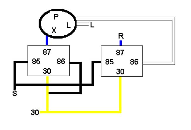


jc_005 Well, the above didn't work. Here's what did. The circuit logic of the earlier workaround was flawed: the current flowing through the relay coils was not enough to get the flasher unit to work, even though it is a variable-load type. This second iteration was an attempt to put two 32cp lights and the associated wiring in the "L" or load circuit of the flasher- that would certainly get it to operate. I had originally considered using two flashers in the 87 terminal outputs from the relays, and tried it, but ended up with different flashing rates-- it looked like a circus car. So then it hit me, I could drive the second relay's coil input with a multiple from the flasher's output, and run them simultaneous, while retaining electrical isolation between the individual turn signal circuits. Remember, the reason to do this rather than just hooking both turn signal circuits to the "L" output of a flasher is that if you did that, you would get both turn signals operating when you just wanted one. The factory can had a DPST relay inside, along with a thermal flasher-- small and effective. In later years, they went to a grounded, electro-mechanical type that ran both turn signals and hazard, and the changeover was in the hazard switch. I also took the opportunity to FIX a major error that some PO had done, and all subsequent PO's missed-- the front turn signals were wired to the bulbs for the parking lights. So rather than a big 32cp lamp at the corner of the car flashing, a wimpy 2cp bulb in the small square next to the horn grill signaled your intention to turn. Not very smart in today's modern traffic. Anyway, it's done. . . not easy to reverse-engineer the Germans of 40 years ago. Attached are pictures. With apologies to those who would have demanded the DIN spec for the wire colors, these were the sockets I had! |

